
RAKER AND WALER CONNECTION DETAILS: FIELD PHOTO NOTES
A closer look at real steel bracing photographs published by Riconstruct, highlighting the connection and sequencing considerations that matter on excavation-support jobs.
These photographs are drawn from Riconstruct's existing public project gallery. They illustrate different field conditions and connection details; they are not presented as one project or a single continuous installation sequence. Customer identities, precise locations and project names are intentionally omitted.
1. Raker positioning and site access
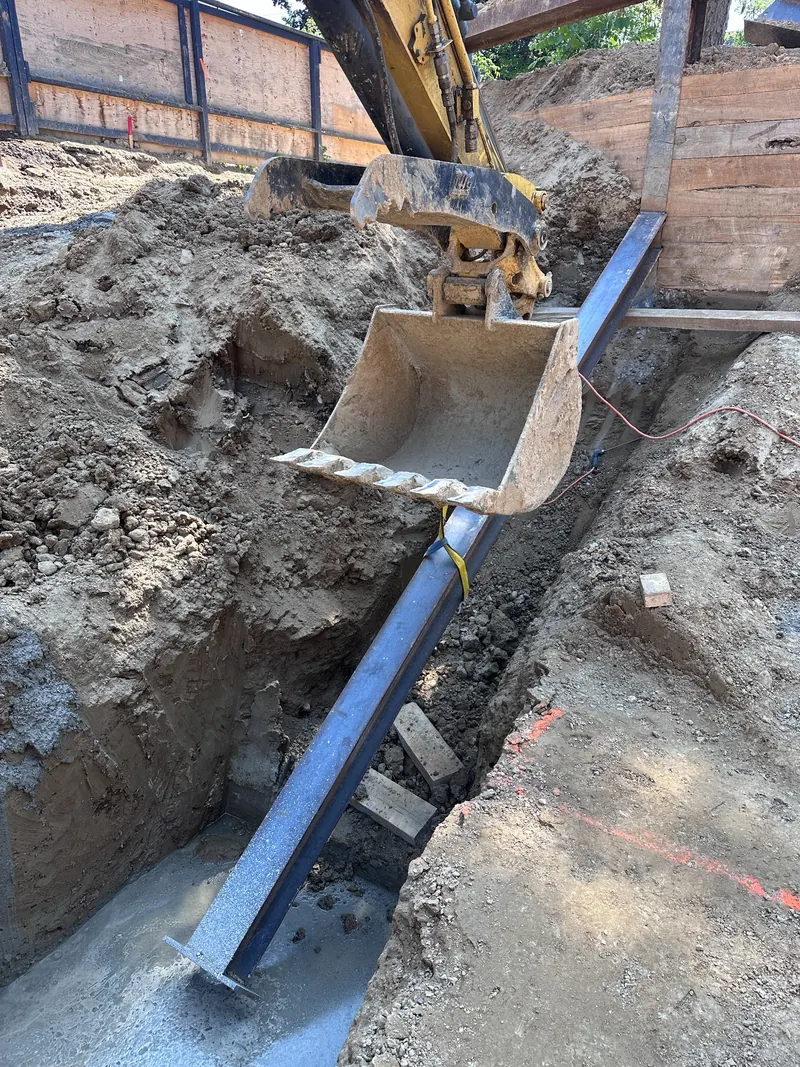
Large raker assemblies must be handled and positioned in coordination with the site's lifting and excavation operations. For a field welding contractor, planning for welding access, joint preparation and the required inspection stage is part of coordinating the scope with the construction team.
2. Support chairs and H-pile connections
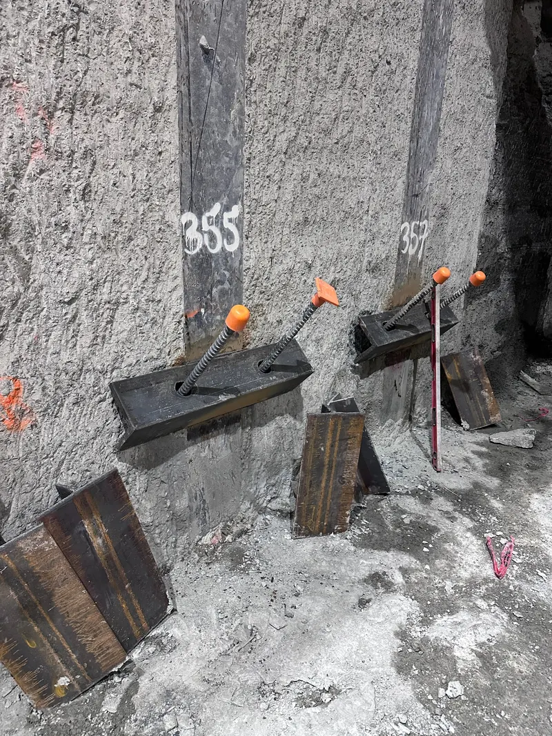
Support chairs and related steel components can form part of the engineered connection between shoring members. Fit-up and access can be challenging where the steel is close to soil retention systems or other structural members.
3. Stubbed-out waler connection and formwork clearance
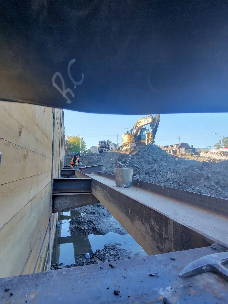
Some projects require waler components to be terminated or staged so that subsequent concrete forming can proceed. This is a good example of why field welding must be coordinated with the larger construction sequence. The exact arrangement is always project-specific.
What contractors can take from these examples
Shoring steelwork brings together engineered connections, heavy members, evolving site access and construction timing. A useful welding scope identifies what is to be fabricated or welded, when access is available, and when the connection must be inspected relative to the next operation.
Privacy and technical note: Images are published with customer and location details omitted. Descriptions are educational observations based on visible site work, not as-built verification or instructions for constructing an excavation-support system.
For an overview of the member roles, read Understanding Rakers and Walers. For project-specific field welding support, see Shoring & Pile Welding.
Need a field welding quote?
Provide the project drawings, connection details, schedule, access requirements and inspection expectations to help define the scope.
Contact Riconstruct →